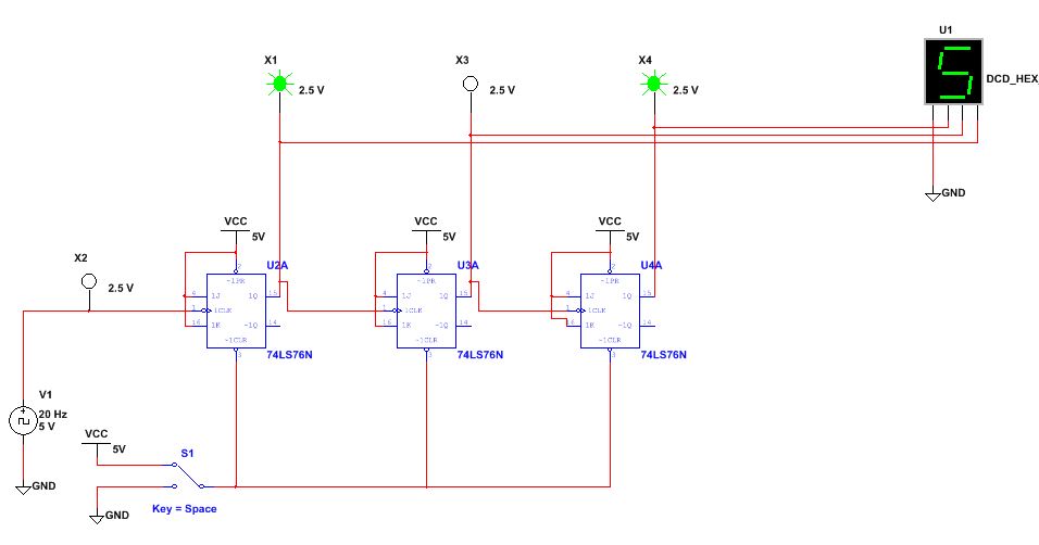
3 bit synchronous binary counter jk flip flop
The J-K flip-flop is the most versatile of the basic flip-flops. It has the input- following character of the clocked D flip-flop but has two inputs,traditionally labeled J and K.
A Synchronous Binary Counter
Power transformers in India Transformer Manufacturer in India. From Silicon to Microprocessor! Monday, December 8, 3-bit Synchronous down counter with JK flip-flops.
Synchronous Counters | Sequential Circuits | Electronics Textbook
This tutorial shows how to design a 3-bit synchronous down counter with JK flip-flops. Construst the state table as below: It is clearly that the count-down function has 8 states. In other words, the design is a MOD-8 counter.
Design a 4-Bit Truncated Sequence Counter (Using JK Flip Flops)This state table does not follow the sequence from low to high but it does follow with the description function of count-down function. It might lead to mistakes when constructing Kmap. JK Flip Flip Characteristic Table.
Excitation Table You must know how to translate JK characteristic table to JK excitatation table as shown in the table above. It is very crucial to start a design with JK flip-flops. By refering to JK charateristic table, the condition can be fulfilled by first and second rows of characteristic table, which JK inputs are 00 and Hence, the J input must be "0" and K input must be "d" don't care in the excitation table.
Construct the state table with corresponding excitation table: With the information from JK excitation table, the state table with corresponding excitation table can be constructed as shown in the first diagram. Kmap It will be wise if the present state of the state table follows correct sequence from low to high as the diagram below to avoid silly mistakes happen when transfering from state table with corresponding excitation table to the Kmap.
Reduce the circuit from 3-input AND gate to 2-input AND gate and the routing is much simple. Simplified 4-bit synchronous down counter with JK flip-flop What are the advantages and disadvantages for this circuit that has 2-input AND gate as compared to the previous design which has 3-input AND gate?
The answers can be apparent if you think the counter with large bits, eg: Posted by IC Designer at Labels counter 1 flip-flop 1 Kmap 1 latch 1 synchronous 1. Useful Links The Digital Electronics Blog. About Me IC Designer icdesignhelp gmail.

Subscribe To Posts Atom. Enter your email address: Feedjit Live Blog Stats.